The two transistor astable multivibrator is a very simple classical circuit.
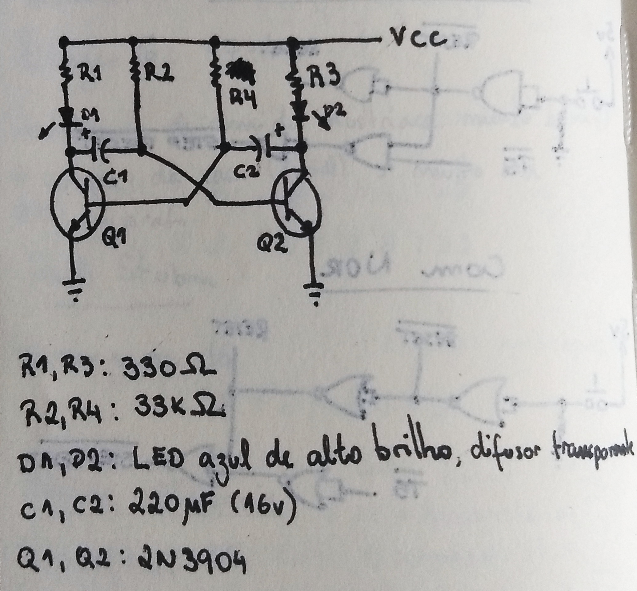
There is a lot of information about it online, but basically the capacitors take turns charging through a resistor, turning on one of the transistors and allowing current to flow through one of the LEDs. When it discharges, the same cycle happens on the other side of the circuit.
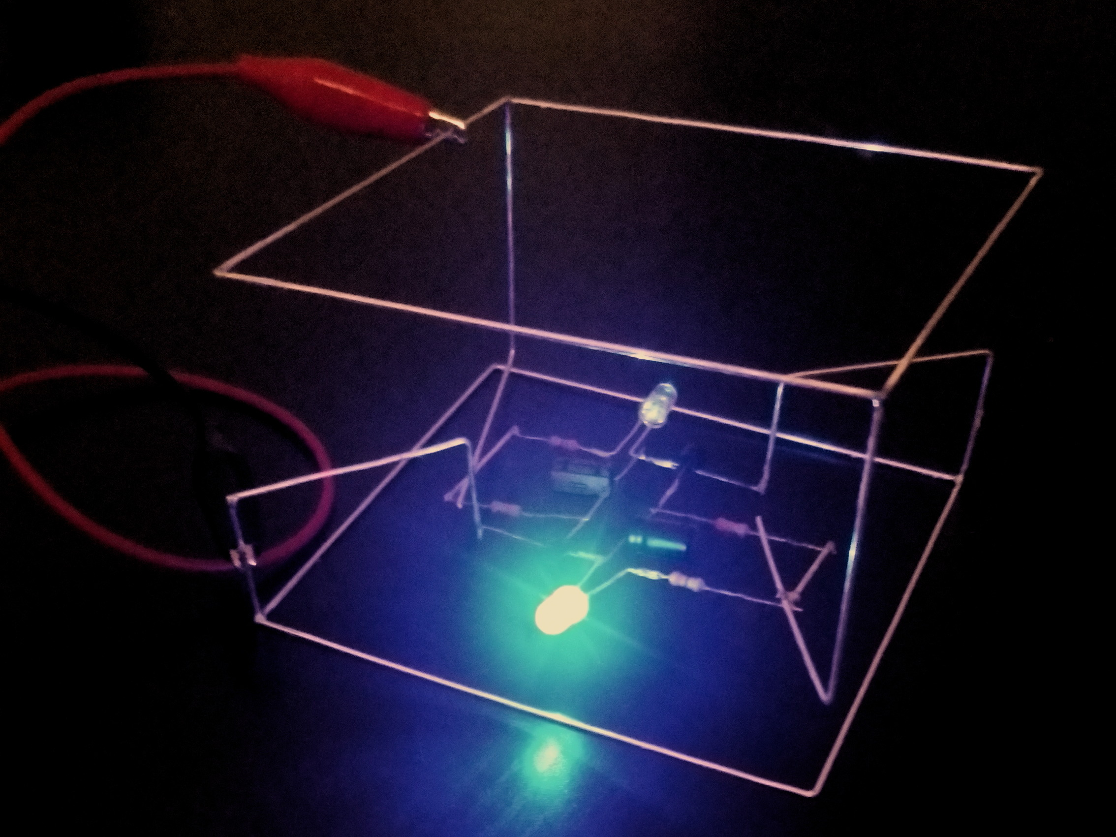
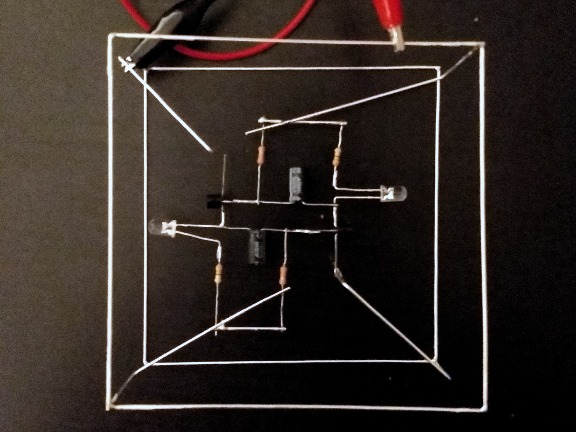
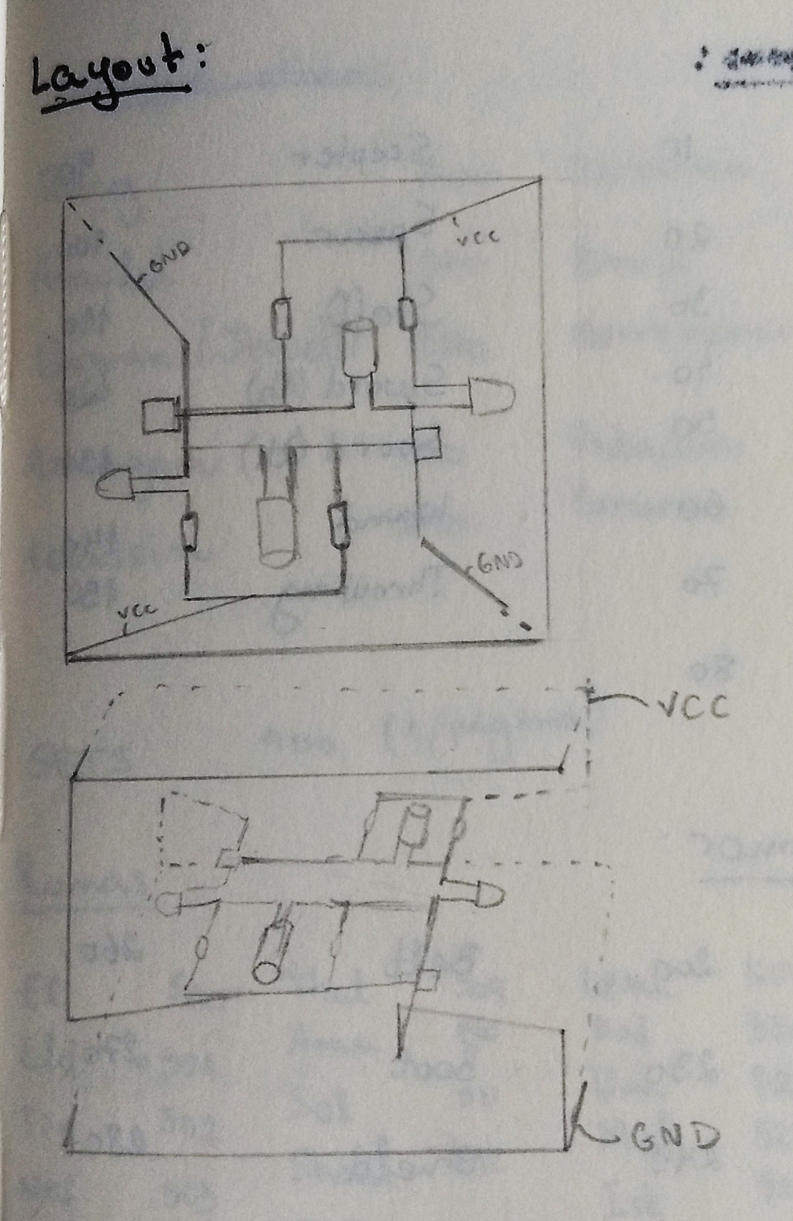
I thought it would be fitting to have some square waves produced by a cube, so that's the shape the circuit took.
And here are some more bad pictures taken with my phone: